
How to Read and Interpret OTDR Traces
Optical Time-Domain Reflectometers (OTDRs) are essential tools for evaluating fiber optic networks. They provide a visual map of the fiber, showing events like splices, connectors, bends, and faults. However, interpreting OTDR traces correctly is key to troubleshooting and maintaining high-performance fiber systems.
In this guide, we’ll explain how OTDR traces work, common events you’ll see, and how to use supporting tools like Loss Testers and Fiber Inspection Scopes for more accurate diagnostics.
What is an OTDR Trace?
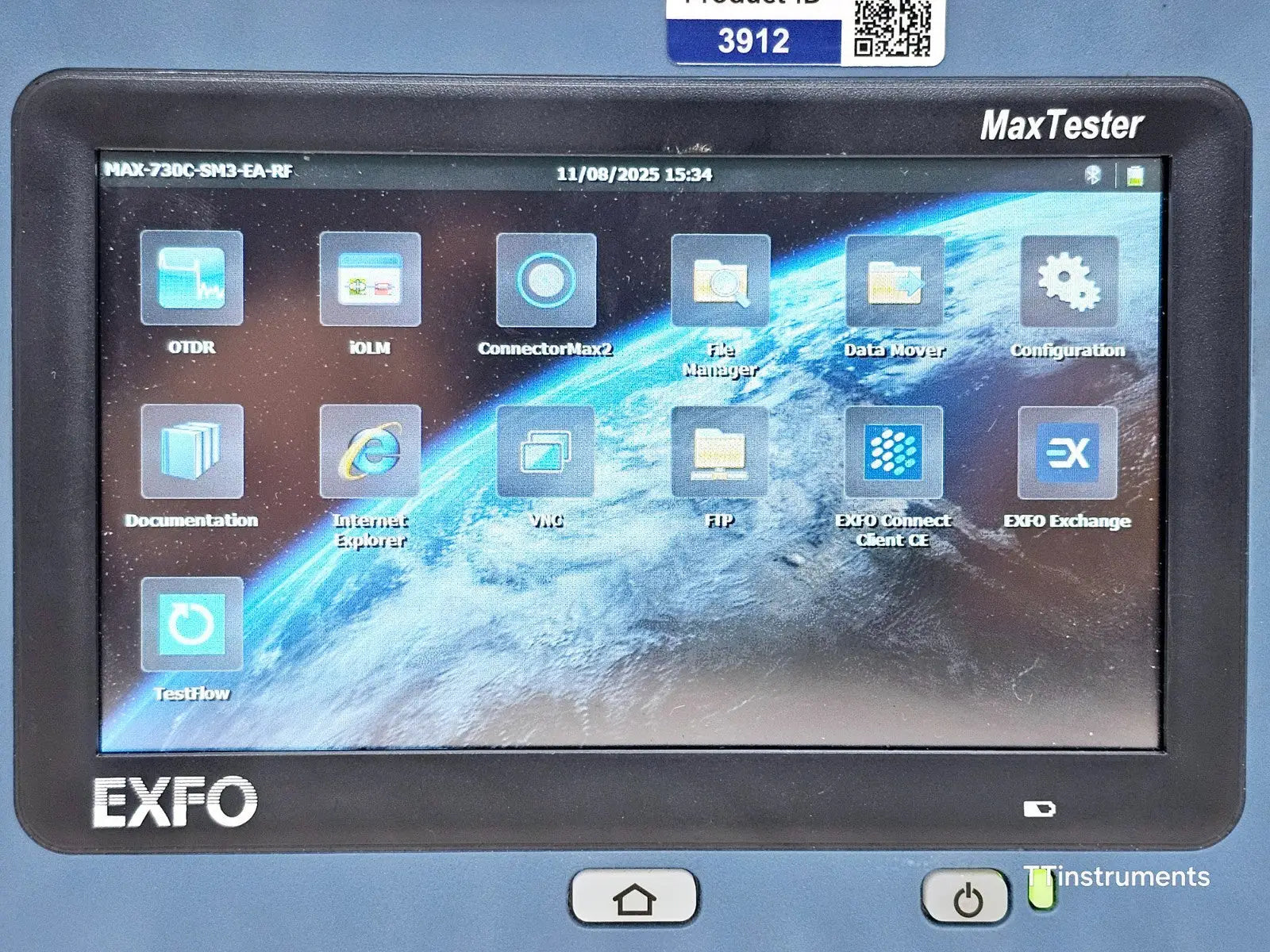
An OTDR sends a series of optical pulses down a fiber and measures the light reflected back. The resulting trace is a graph showing signal power versus distance along the fiber. Peaks, dips, and slopes on the trace correspond to events such as:
-
Splices and connectors: Slight losses appear as small dips.
-
Bends or microbends: Cause gradual attenuation over a section.
-
Breaks or major faults: Appear as sudden, sharp drops in power.
Each OTDR model may display traces differently, but the principles remain the same.
Key Features to Look at on the Trace
-
Event Loss – The optical loss at a specific splice or connector.
-
Attenuation – Gradual loss per kilometer of fiber, indicating fiber health.
-
Reflectance – High reflections may indicate poor connectors or end-face contamination.
-
Distance to Event – Helps pinpoint exact locations of faults for repair.
Using Loss Testers and Fiber Inspection Scopes
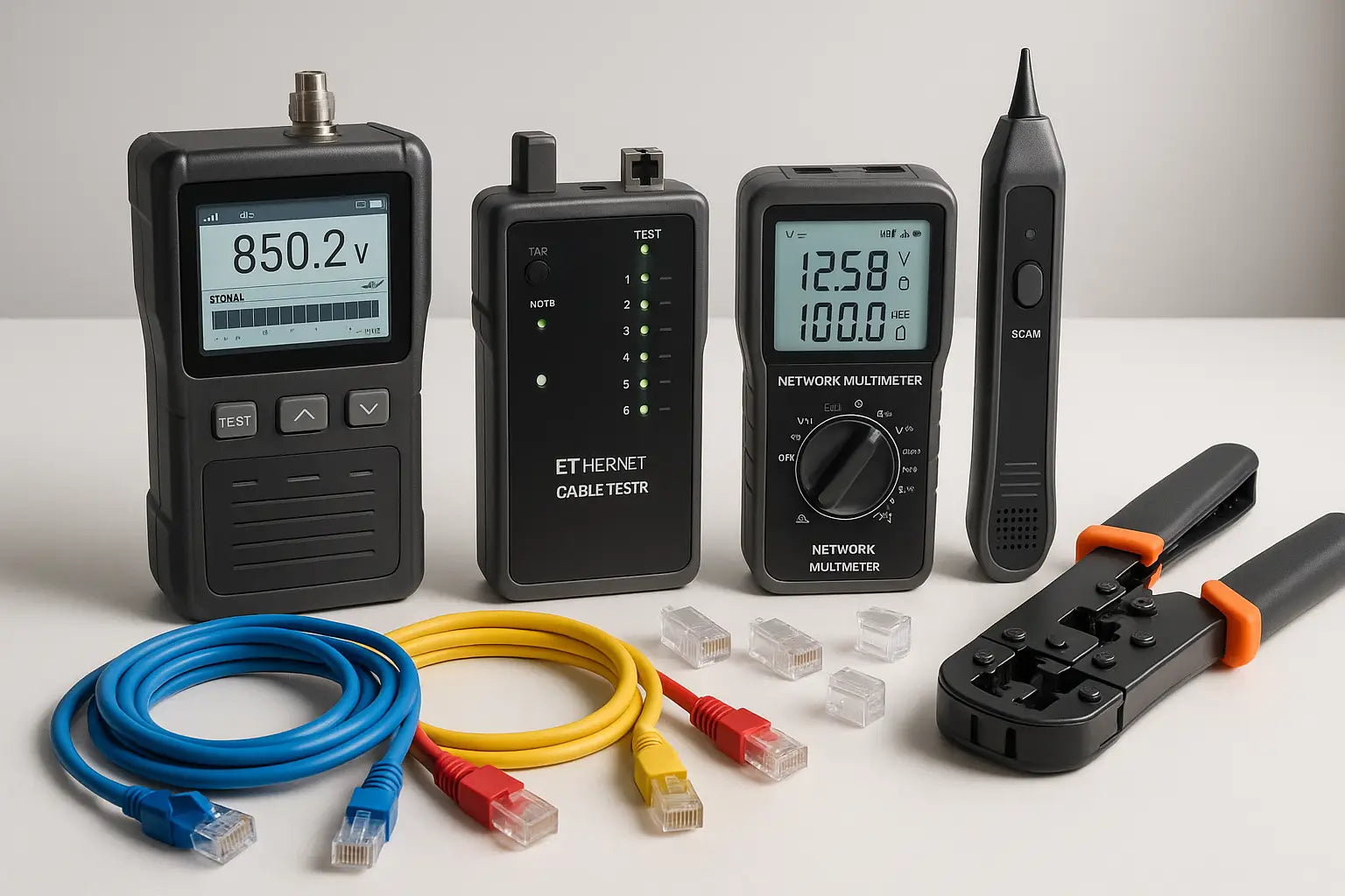
While OTDRs give a broad overview, additional tools provide detailed insight:
-
Loss Testers & Optical Power Meters: Confirm end-to-end loss values to validate OTDR findings.
-
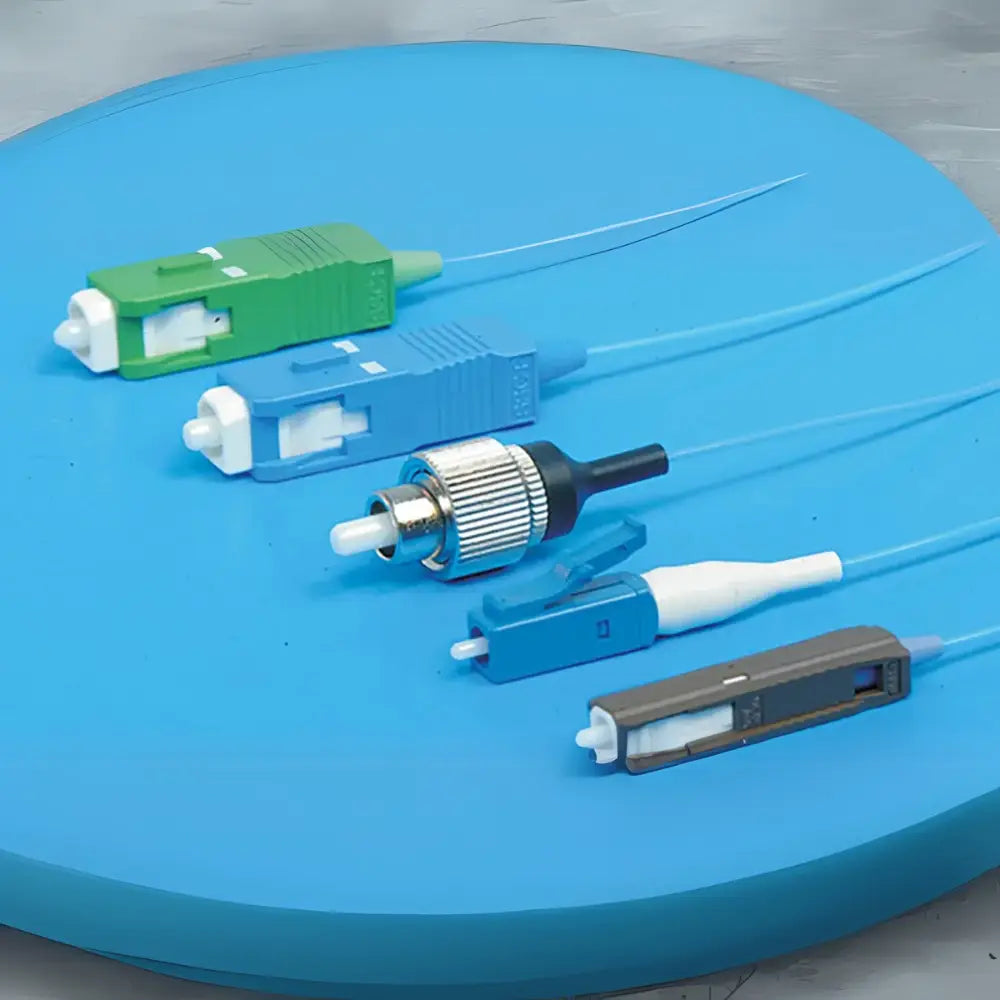
Fiber Inspection Scopes: Inspect connector end faces to detect dirt, scratches, or misalignment that may cause reflection or loss.
Combining these tools ensures a more complete and accurate diagnosis of the fiber network.
Best Practices for OTDR Measurements
-
Always clean connectors before testing.
-
Use proper launch and receive fibers to avoid dead zones at the start and end of the trace.
-
Compare traces to previous measurements for trend analysis.
-
Ensure OTDR settings (pulse width, range, and refractive index) match the fiber type.
Shop Fiber Optic Test Equipment at TT Instruments
TT Instruments offers a wide range of fiber optic testing tools, including:
-
OTDRs for comprehensive fault location
-
Loss Testers for quick end-to-end loss measurement
-
Fiber Inspection Scopes for connector inspection
-
Light Sources, Power Meters, and Visual Fault Locators
Whether you’re troubleshooting, certifying installations, or maintaining fiber networks, we provide new and professionally tested used equipment for reliable performance.
Interpreting OTDR Traces with Confidence
Mastering OTDR trace analysis takes practice, but combining it with supporting tools ensures accurate fault detection and optimized network performance. Regular testing, paired with proper maintenance, keeps fiber networks running smoothly.
FAQs:
1. What does an OTDR trace show?
It plots optical power versus distance along the fiber, indicating events like splices, connectors, bends, and breaks.
2. How do I identify a fiber break on an OTDR trace?
A fiber break appears as a sharp drop in power with no reflected light beyond that point.
3. Why use a Fiber Inspection Scope with an OTDR?
Inspection scopes let you check connector end faces for dirt or scratches, which can affect OTDR readings.
4. What is event loss and how is it measured?
Event loss is the optical power loss at a splice or connector, calculated by the difference in signal before and after the event.
5. Should I use a launch fiber with an OTDR?
Yes, a launch fiber helps avoid blind spots at the start of the measurement, ensuring accurate results.
%20are%20essential%20tools%20for%20evaluating%20fiber%20optic%20networks.%20They%20provide%20a%20visual%20map%20of%20the%20fiber,%20showing%20events%20like%20splices,%20connectors,%20bends,%20and%20fault...)